<img alt="" src="https://secure.smart-enterprise-365.com/779147.png" style="display:none;">
3dcs-suspension-automotive-1

3DCS Mechanical Variation Modeler

Mechanical Tolerance Analysis 

3DCS Mechanical Variation Modeler (MVM) Mechanical focused version of 3DCS designed with Joints & Constraints 

Integrated into CATIA V5, NX, 3DEXPERIENCE, CREO, and SOLIDWORKS and stand-alone Multi-CAD

Download Brochure

Advanced Mechanical Tolerance Stack Up Simulation

Mechanical Tolerance Analysis for Design Engineers of Rigid Structures and Mechanical Assemblies

3DCS Mechanical Variation Modeler Software is designed to be easy to use with Joints and Constraints

3DCS Mechanical Variation Modeler is built on the 3DCS platform incorporating 3DCS Mechanical Modeler into its base functionality to model complicated linkages and mechanical assemblies with easy-to-apply Constraints, Joints, and a DCS Feature Move. 

By modeling the assembly process, and determining the risk and source of part failures, manufacturers can optimize their design to account for both process and part variation, reducing non-conformance, scrap, rework, and warranty costs. 

3DCS Mechanical Variation Modeler - What is it?

3dcs-mechanical-mva-suspension3DCS Mechanical is a standalone or CAD integrated application, designed as a less complex tool compared to 3DCS Variation Analyst, and focused on mechanical joints and constraints to make modeling more intuitive for mechanical assemblies.

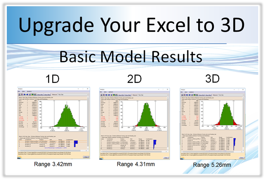
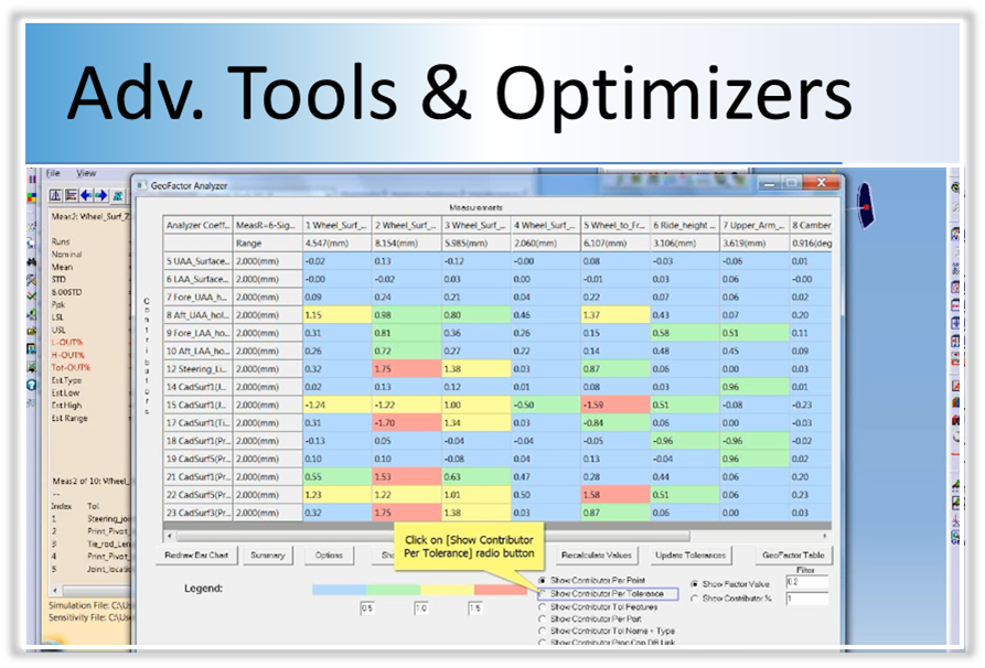
3DCS Mechanical Variation Modeler, just like 3DCS Variation Analyst, gives outputs based on part and process variation. These can be input in a variety of ways, from CAD-based PMI, extracting Joints and Constraints from CAD, to selecting feature and point-based options in the software. The final results are shown as statistical (Monte Carlo) and mathematics (Sensitivity) based outputs with toggle-able metrics including Cpk, Ppk, ranges, percent out of specification, and a variety more. 

3DCS Mechanical Variation Modeler Value: 

  • Model complicated linkages and mechanical assemblies
  • Combine 3D Variation and Kinematic Mechanical Analysis
  • Depict variation on kinematic assemblies through their range of motion in place of fixed locations 
  • Simplify modeling with access to a library of common joints and constraints

Model Part and Process Variation - How does it work?


Mech_suspension-highlighted3DCS Mechanical Variation Modeler uses two methods of simulation;

  1. Monte Carlo Simulation,
  2. Sensitivity analysis

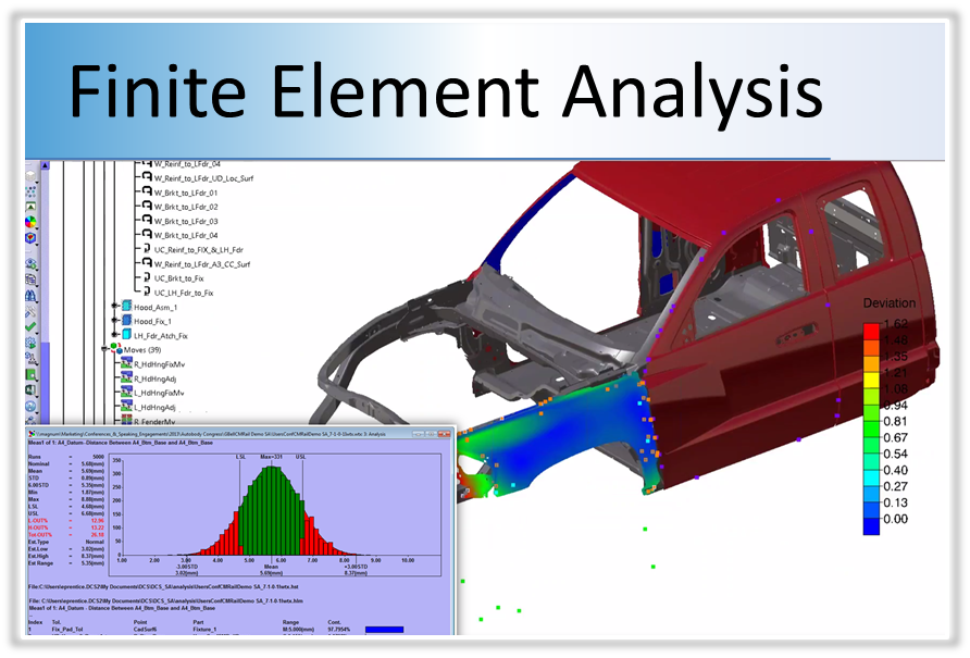
These analyses determine both the sources of variation as well as potential build issues in the product.

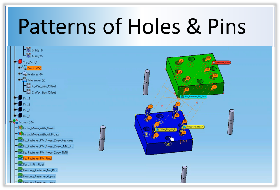
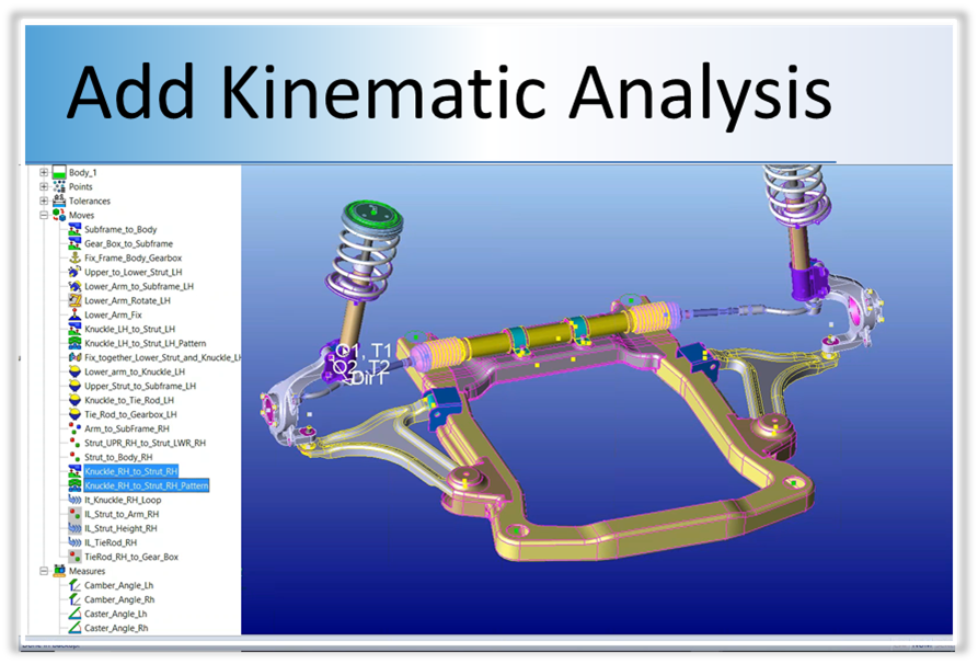
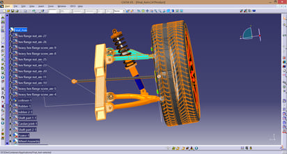
As a mechanical and kinematic based tool, 3DCS Mechanical utilizes the same joints and constraints as the 3DCS add-on module Mechanical Modeler. These functions allow the modeling of mechanical movements and analysis through a range of motion to determine the effect of variation on product function. 

Modeling the build process in addition to their part tolerance stack-up, users can determine how the variation will affect the assembly. This together creates a true Digital Twin that can be used to make decisions about design changes and tooling while reducing scrap and rework. 

What is in a 3DCS model? Click to Learn More

Find Design Defects Early in the Product Lifecycle

Cost of Quality Across PLMIt is well known that the earlier in the Product Lifecycle an issue is found, the cheaper it is to fix. When a product is still in the digital design phase, an engineering change can be as simple as a click of a mouse. However, as soon as the product gets into the customers' hands though, a simple engineering change may mean recalls and warranty claims. This costs exorbitantly more than updating a CAD model. 

Creating digital twins for tolerance analysis has become an important part of many OEM's product development processes. CAD simulation and analysis gives engineers the opportunity to validate their assembly process and tolerances early in the Product Lifecycle, and to make relevant, inexpensive changes before tools are cut. Simulation, optimization, and validation in the digital environment has been proven to save millions of dollars in production costs, and this number only grows as both the tools and the users become more advanced. 

PART OF THE DCS SCALABLE SOLUTION


dcs-scalable-solution-complexity

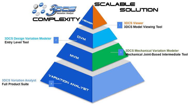
Expand Tolerance Analysis across your organization with the DCS Scalable Solution, leveraging Model-Based Definition to drive quality downstream. 

Leverage Your 3D Tolerance Analysis with 3DCS Advanced Features and Add-on Modules

pattern-move-heading-1-1
Analyze Complex Hole / Pin Patterns
No Add-ons Needed!
upgrade-tolerance-analysis-from-excel-1
Why Upgrade from Excel?
Learn what Excel is missing
3dcs-finite-element-analysis-1
Analyze Flexible Parts and Assemblies
3DCS FEA Compliant Modeler Add-on
3dcs-aao-advanced-analyzers-and-optimizers
Add 6 Advanced Analyzers & Optimizers
3DCS AAO Add-on
3dcs-mechanical-modeler-add-on-kinematics
Model Mechanical Joints, Constraints, Kinematics
3DCS Mechanical Modeler Add-on
3dcs-perceived-quality-1
View Variation with Photo Realism
3DCS Visualization Export Add-on

Key Product Highlights

Integrated in CATIA V5 & V6 3DEXPERIENCE
Integrated in SOLIDWORKS
Integrated in PTC CREO
NX-transparent-bkgrnd
Use Native INVENTOR Files with Multi-CAD

3DCS Key Features

How does 3DCS help you reduce lead times, scrap, and rework?

Validate & Optimize GD&T - Pull in Embedded GD&T (PMI) & Joints and Constraints

Utilize the CAD Platform to Reduce Re-authoring of Data 

3DCS Mechanical Variation Modeler reads in GD&T (PMI / FTA), and Joints and Constraints to quickly tolerance and build your Tolerance Analysis models. This is a fast and effective way to begin your analysis, but also gives engineers the ability to validate the GD&T (PMI) and optimize it to improve product quality by tightening and testing areas critical to build quality. Additionally, understanding which areas of the product are critical, and which are non-critical to quality, allows the user to reduce manufacturing costs, by increasing (loosening) tolerances in non-critical areas. 

Values:

  • Create and start analyzing faster with embedded GD&T (PMI)
  • Read in Joints and Constraints to assemble the product
  • Determine which areas are critical to your build quality to focus on and measure
  • Save money by loosening non-critical tolerances (and make your suppliers happy)
suspension-fta-gdandt

Model Quickly - Utilize a Library of Joints and Constraints for Fast Modeling

Pick from the extensive library of Joints and Constraints to quickly model your product

3DCS Mechanical Variation Modeler comes loaded with a library of common Joints and Constraints to apply to your model. These intuitive Moves make assembling your model faster and easier. As an integrated product, Designers can utilize their knowledge of CAD Joints and Constraints to take their design a step further with tolerance analysis and variation simulation. 

Values:

  • Pick from common Constraints to constrain the model 
  • Assemble the model with an intuitive library of Joints 
  • Build mechanical assemblies quickly 
DCS MVM Mechanical Move library

Reduce Risk - Find the Source of Variation and Improve Quality Through Iteration

Determine the true source of build issues and then solve those issues through iterative design changes

Use 3DCS software to hone in on the source of variation, and then use iterative design changes to optimize your product for manufacture and assembly (DFMA - Design for Manufacture and Assembly). 

Making changes to the design based on your simulation results, the answers become a button push away. Change the design in your CAD, adjust tolerances, change assembly processes, and quickly see the results. Compare and contrast different build strategies, locators, datum plans, tolerances, and other inputs to see how they affect your final product. 

Values:

  • Determine the source of variation and the risk of build issues
  • Apply iterative design changes to compare and contrast different plans, and then optimize for the highest quality and lowest cost
3dcs-mechanical-mva-suspension-check-analysis

Communicate - Collaborate and Present with One Button Reports

Generate either in-depth reports to collaborate with your team, or simpler summary reports to present to management with the push of a button 

Create the reports you need from 3DCS with the push of a button: html, pdf, PowerPoint ppt or Excel. Use the reports to share information with colleagues, present on progress and your modeling strategy, to archive the model's information and inputs, or to summarize the results for managers and customers. 

These reports are powerful tools for business as well. Used to generate coordinated measurement plans, they can be used to standardize measurement procedures and CMM routines for suppliers and OEM's. Use your reports instead to negotiate tolerances with your customers, whether they are suppliers, or OEM's, showcasing why tolerances need, or can be, loosened or tightened. 

All of this without having to spend hours and days compiling images and data. With the push of a button, you have all the information you need. Customization options let you configure your outputs to meet each need, letting you create a variety of reports and outputs from a single model.  

Values:

  • Collaborate with team members and managers 
  • Standardize measurement and CMM plans 
  • Use data to drive discussions with supplier and OEM customers

Click Here to View a Tolerance Analysis Report Example

MVM One Button Report

Digital Twin - Simulate Fixtures, Tooling, and Processes 

Add tooling to your analysis, along with manufacturing processes, and multi-stage assemblies

Find the source of variation, honing in on either particular part tolerances, or processes. Many times the source of variation is in the assembly process and the solution does not require the changing of tolerances. This can give engineers the ability to improve quality without having to make costly tolerance adjustments. In addition, tolerance and process changes can be made in the model and simulated to find optimal conditions to get the greatest increase in quality at the lowest cost. 

Value:

  • Find primary source of variation issues from either tolerances or assembly process
  • Make changes and determine the affect of variation
  • Use iterative changes to create the optimal design for maximum quality and minimum cost
Suspension in 3DCS MVM Multi-CAD

GeoFactor - Analyze the Relationship Between Components

Find the multiplicative effect on tolerances from assembly geometry

Determine the geometric relationship between tolerances and the overall assembly. How much of an effect will changing particular tolerances have on the product's dimensional quality?

Click to Learn More about GeoFactor Analysis

3DCS Analysis - GeoFactor Highlight
Advantages during the pre-production phase are root cause analysis - only recently we've actually really started using the software to root cause the problems. We've found that looking at the contributor lists, for example, really help us get to the root cause of the problems and propose solutions.”

Laurence Allmark

Senior New Product Quality Engineer, McLaren Automotive

Learn More with Webinars and Articles

Learn more about 3DCS and upcoming webinars from the DCS Blog - Engineering Talk

Ready to start a project?

Let DCS help you realize the benefits of 3DCS tolerance simulation
CONTACT DCS