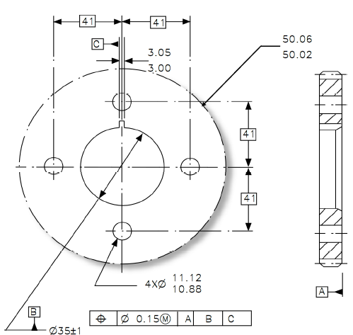
GD&T Geometric Dimensioning and Tolerancing is defined as an international language used for communicating engineering design specifications based on the function and intent of part features. This engineering language uses the necessary definitions, symbols, and application rules to clearly document the nominal geometry as well as the acceptable variation of the features. This includes the functional requirements of a manufactured assembly part and to ensure the compatibility and interchangeability of those parts.
GD&T is codified by the ASME - The American Society of Mechanical Engineers - https://www.asme.org/
The Y14.5 standard is considered the authoritative guideline for the design language of geometric dimensioning and tolerancing (GD&T.) It establishes symbols, rules, definitions, requirements, defaults, and recommended practices for stating and interpreting GD&T and related requirements for use on engineering drawings, models defined in digital data files, and in related documents.
GD&T is an essential tool for communicating design intent — that parts from technical drawings have the desired form, fit, function and interchangeability. By providing uniformity in drawing specifications and interpretation, GD&T reduces guesswork throughout the manufacturing process — improving quality, lowering costs, and shortening deliveries.
--- ASME Website - https://www.asme.org/codes-standards/find-codes-standards/y14-5-dimensioning-tolerancing?productKey=N00518:N00518
GD&T provides the links between theoretical 3D models, CAD (Computer GD&T is the tool for precisely and clearly defining functional specifications for size, form, orientation Aided Design), CAM (Computer Aided Manufacturing) and CAI ((Computer Aided Inspection) and the real world; and location of the elements of a manufactured part.

With proper application, GD&T communicates a coordinated understanding to the Design, Manufacturing, and Quality Engineering teams as well as all suppliers and/or customers.
GD&T is a tool of dimensional management as well as tolerance analysis (1D stacks, 3D stacks, CAD based tolerance analysis). The goal is to validate during design, that if your parts are in spec, and you build it per intent, you will meet your assembly requirements dimensionally.
GD&T provides a common language to communicate specifications across the organization in a clear manner that can be interpreted the same throughout the entire product life cycle. This provides a variety of benefits when implemented correctly:
Improve Quality by coordinating part specifications with end product design requirements.

Reduces manufacturing costs by opening tolerances on noncritical features.

Simplifies part verification process and PPAP.
Specifies and communicates requirements more precisely.

Click Here to Learn More About the Value of GD&T Implementation
GD&T is applied using symbols and Datums. Click below to see common symbols, and to better understand Datums and Material Conditions
The best to place to start is to discuss implementation with an expert. DCS and its partners across the globe have ASME certified trainers who can discuss implementation, adoption, best practices, and provide training courses to get your people up to speed.