<img alt="" src="https://secure.smart-enterprise-365.com/779147.png" style="display:none;">
3DCS automotive analysis

3DCS Variation Analyst

Multi-CAD | Stand-Alone

CAD Neutral Tolerance Simulation

Work With Any CAD System

Download Brochure

Advanced Tolerance Stack Up Simulation

The Leading Tolerance Analysis Solution - What is it?

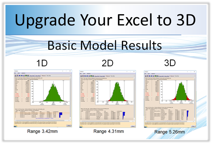
3DCS Variation Analyst Multi-CAD is a stand-alone tolerance analysis software solution that simulates product assembly and part tolerance 3D stack-ups through Monte Carlo Analysis and High-Low-Median (Sensitivity) Analysis.

3DCS Multi-CAD simulates part and process variation with Monte Carlo Simulation to give statistical outputs showing the estimated percent of products that will be out-of-spec, the primary contributing tolerances and parts to variation issues, and specified statistical measures such Cpk and Ppk. 

Use Any Native CAD, STEP, or IGES

3DCS Multi-CAD uses TransMagic translators to analyze models from any CAD system. This allows companies who juggle multiple CAD systems to use any CAD file for their tolerance analysis. 

Model Assembly Process and Part Tolerances - How does 3DCS work?

3DCS Variation Analyst Multi-CAD uses three methods of simulation;

1. Monte Carlo Simulation

2. High-Low-Median (Sensitivity analysis) 

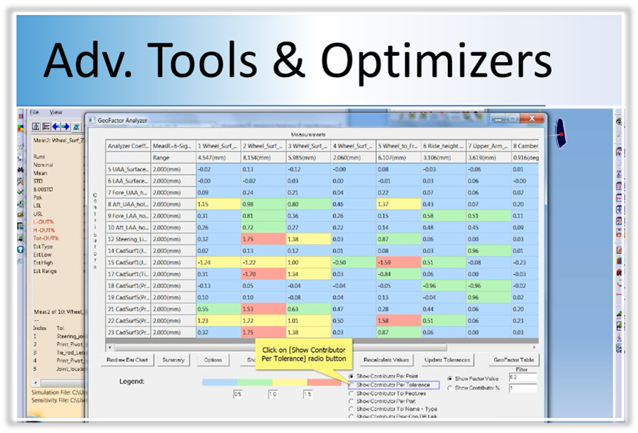
3. GeoFactor (RSS equation) Analysis

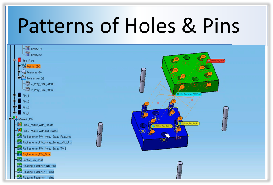
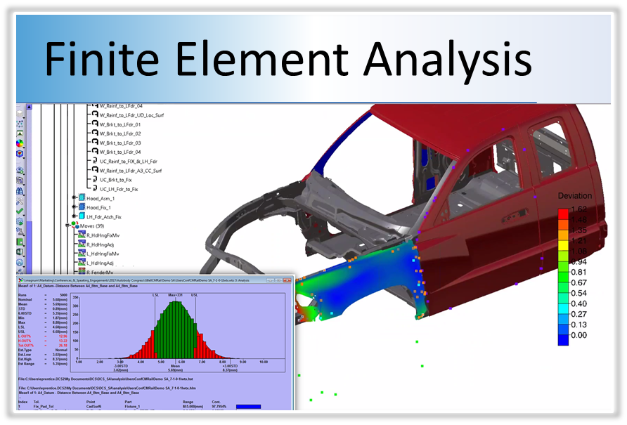
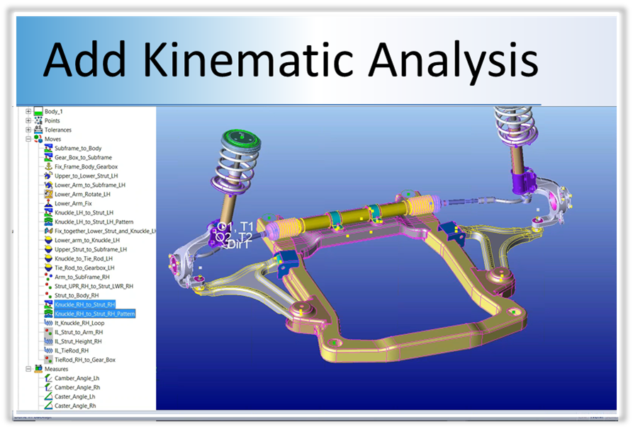
By accurately modeling the assembly, you can see how both the assembly process and the part tolerances contribute to the product's overall variation.  Together, this creates a virtual prototype that can be used to make decisions about design changes and tooling while reducing non-conformance that leads to scrap and rework. 

How does 3DCS Work? Watch the FREE video series on 3DCS

Gain Greater Insight Into Your Design

Simulating products in a digital environment gives engineers the ability to account for variation in key areas; reducing rework, non-conformance, and scrap at final assembly early in the design phase when changes are least expensive.

The Cost of Quality in PLM

In addition to this, specifications deemed less critical can be relaxed, increasing tolerances and allowing the use of less expensive manufacturing processes. Creating 3-dimensional tolerance stack-ups let engineers know where to focus when measuring and designing, and the ability to create what-if studies allow them to determine solutions that include both process and part tolerances to keep quality high and costs down. 

PART OF THE DCS SCALABLE SOLUTION

dcs-scalable-solution-complexity

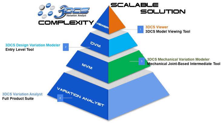
Expand Tolerance Analysis across your organization with the DCS Scalable Solution, leveraging Model-Based Definition to drive quality downstream. 

Leverage Your 3D Tolerance Analysis with 3DCS Advanced Features and Add-on Modules

Analyze Patterns of Holes and Pins
Analyze Complex Hole / Pin Patterns
No Add-ons Needed!
1D Excel Stacks under report variation
What 1D Excel Stacks are Missing
Stop doing 1D Excel Stacks
Add Finite Element Analysis to 3DCS
Analyze Flexible Parts and Assemblies
3DCS FEA Compliant Modeler Add-on
Add additional analyzers and optimizers to 3DCS
Add 6 Advanced Analyzers & Optimizers
3DCS AAO Add-on
Add mechanical joints and constraints to 3DCS
Model Mechanical Joints, Constraints, Kinematics
3DCS Mechanical Modeler Add-on
Utilize Visualization for Perceived Quality
View Variation with Photo Realism
3DCS Visualization Export Add-on

Key Product Highlights

3DCS Multi-CAD is an advanced analysis tool giving you the information to make important decisions on quality

Integrated in CATIA V5 & V6 3DEXPERIENCE
Integrated in SOLIDWORKS
Integrated in CREO
Integrated in NX
Analyze INVENTOR CAD Models

3DCS Key Features

How does 3DCS help you reduce lead times, scrap, and rework?

PMI - Validate and Optimize GD&T 

Utilize Embedded GD&T (PMI)

3DCS Multi-CAD can use PMI (Product Manufacturing Information) and embedded GD&T from your CAD to instantly tolerance your parts. Simulate the build to validate your tolerances, then make adjustments to optimize for cost, quality, and variation control. Once complete, push your tolerances back to CAD and update your models. 

Value:

  • Build analysis models faster (embedded GD&T is not required for a model)
  • Push button import of CAD GD&T
  • Validate and optimize your GD&T in 3DCS as a test lab, then push back when ready
3DCS Study - Validate & Optimize GD&T

Perceived Quality - Determine Design Objectives with Visualization

Reduce the need for expensive prototypes

Create life-like images of your product showing worst case scenarios to determine the visual impact of variation stack-ups. Use these studies to determine maximum and minimum tolerances during design and communicate with engineering. Once engineers have determined the manufacturing tolerances, recreate the studies to see how your actual product will look with worst case tolerance stack-ups. These studies together help you improve the Perceived Quality of your product as well as your build quality. 

Value:

  • Determine the impact of variation on the appearance of your product
  • See what worst case scenarios will look like on final product
  • Improve both build and perceived quality of products
3DCS Perceived Quality Study

Reduce Risk - Find Contributors and Make Iterative Design Changes

Find the sources of your variation and simulate your changes to determine impact

Find the source of variation, honing in on either particular part tolerances, or processes. Many times the source of variation is in the assembly process and the solution does not require the changing of tolerances. This can give engineers the ability to improve quality without having to make costly tolerance adjustments. In addition, tolerance and process changes can be made in the model and simulated to find optimal conditions to get the greatest increase in quality at the lowest cost. 

Value:

  • Find primary source of variation issues from either tolerances or assembly process
  • Make changes and determine the affect of variation
  • Use iterative changes to create the optimal design for maximum quality and minimum cost
Study Assembly and Variation with 3DCS

Communicate - Create Reports and Measurement Plans to Collaborate

Streamline the creation and communication of measurement plans and results

Use reports and measurement plans to communicate results across the organization. Detailed engineering reports communicate with other design teams the inputs and outputs of the model so that the results can be repeated and understood. Management Reports communicate the key outputs to managers to support key decision making. Measurement Plans communicate important areas and particular points to be measured at the plant or CMM room to control variation and watch for out-of-spec and non-conformance conditions. 

Value:

  • Quickly communicate detailed inputs and outputs with customers and other teams
  • Share key outputs with managers to support important decision making
  • Create Measurement Plans tied to CAD for the manufacturing plant to use in order to control and monitor variation effectively in production, answering the question, 'Where should we measure?'
Create GD&T Sheets and Measurement Plans

Digital Twin - Simulate Fixtures, Tooling, and Processes 

Add tooling to your analysis, along with manufacturing processes, and multi-stage assemblies

Find the source of variation, honing in on either particular part tolerances, or processes. Many times the source of variation is in the assembly process and the solution does not require the changing of tolerances. This can give engineers the ability to improve quality without having to make costly tolerance adjustments. In addition, tolerance and process changes can be made in the model and simulated to find optimal conditions to get the greatest increase in quality at the lowest cost. 

Value:

  • Find primary source of variation issues from either tolerances or assembly process
  • Make changes and determine the affect of variation
  • Use iterative changes to create the optimal design for maximum quality and minimum cost
3DCS Multi-CAD Suspension Study

GeoFactor - Analyze the Relationship Between Components

Find the multiplicative effect on tolerances from assembly geometry

Determine the geometric relationship between tolerances and the overall assembly. How much of an effect will changing particular tolerances have on the product's dimensional quality?

Click to Learn More about GeoFactor Analysis

3DCS GeoFactor Highlight
The 3DCS technology brought our commitment to product quality and safety by design to an even higher level. The tool not only can quantify our technical decisions but truly helps our IPD teams to numerically and visually discuss spatial dimensional variations and its management early in the design phase.

Daniel C. da Silva

Embraer Tolerance Analysis Team LeaderEmbraer

Learn More with Webinars and Articles

Learn more about 3DCS and upcoming webinars from the DCS Blog - Engineering Talk

Ready to start a project?

Let DCS help you realize the benefits of 3DCS tolerance simulation
CONTACT DCS