Geometric Dimensioning and Tolerancing GD&T is a tool for communicating quality in order to reduce quality costs. These costs are most often from scrap, rework, and warranty recalls dealing. GD&T combats these in a variety of ways.
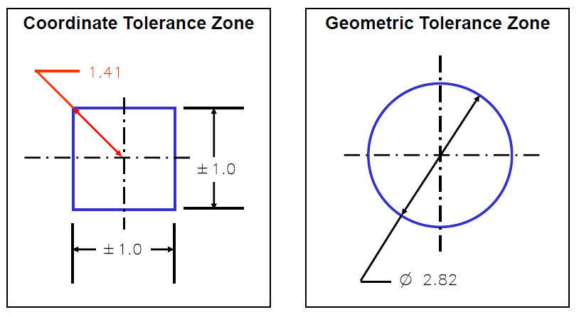
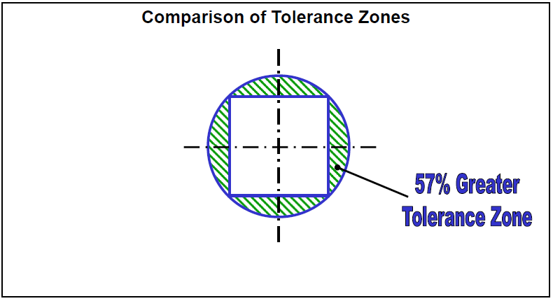
GD&T originated as a method to improve inspection methods of round features. By utilizing GD&T versus coordinate tolerance zones on circular features, the GD&T method increases the acceptable zone by 57%, increasing the amount of acceptable inspections on parts. With standard coordinate zones, when inspection points are in these exterior zones, outside the coordinate area defined by XY callouts, parts are rejected as being out of specification despite them being functional parts. These parts may be unnecessarily scrapped or reworked.
Geometric Dimensioning and Tolerancing GD&T provides a singular language for interpreting specifications and inspection methods. This provides a single method of interpretation, as opposed to notes, standard dimensions that leave too much room for interpretation that can cause disconnects between design, engineering, manufacturing, and inspection.

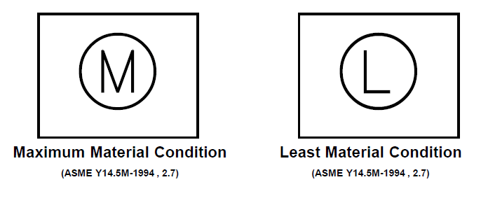
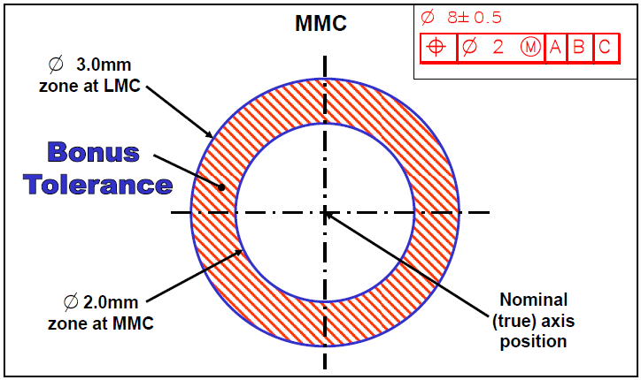
GD&T incorporates additional sources of variation not inherent to standard dimensions. This includes Bonus Tolerance and Material Conditions. The use of software tools to optimize GD&T to open tolerances (increase values) on non-critical features, and create more detailed GD&T to better describe complex or critical features to ensure correct fabrication and inspection.
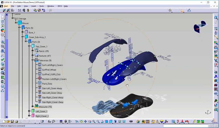
GD&T can be incorporated into a Model-Based Definition approach by creating on the 3D model and then utilizing it as part of PMI to feed downstream systems, ensuring correct communication of quality specifications and reducing the amount of re-authoring that brings additional risk into the system.
Standardizing on GD&T provides a single language for all drawings and models. This keeps different groups from using different notes and annotations to describe features, which can cause confusion and make it difficult to incorporate parts and assemblies from different groups into a single product.
GD&T is not a simple element to incorporate into a company. It requires that the entire company be a part of training, so that GD&T becomes integrated into the culture. Everyone at the company has to be mindful of quality, and their part in it, as well as willing to adhere to the processes required for GD&T to be functionally effective. Without it being brought into the company as a whole, the use and communication aspects, the greatest value, may be lost. This lack of adoption is the most common failure for GD&T initiatives, but not the only one.
Additionally important is the understanding that different groups need to understand GD&T differently. The engineering group designing the GD&T needs to understand it in a holistic fashion; understanding how all the parts are incorporated into a larger assembly and writing the GD&T with this in mind. This is key to setting locators and datums, to understanding if certain features become inaccessible during assembly, and the process by which the part will be incorporated into the larger whole. This is different than the tool maker and the manufacturing team, who need to understand how to read the GD&T to reverse engineer it in order to understand how they need to make their tools, and how the part needs to be fabricated. This provides an understanding of such things as the order of holes to be drilled, the way the part will be located to tooling, and therefore that tools design, and how the part will be set for inspection.
This different understandings require different training. One of the greatest pitfalls is a one-size-fits-all approach to GD&T, with the assumption that all trainees will be using GD&T the same. This only prepares one subset for how GD&T is going to be used day-to-day, and often assures the failure of the initiative.
Use the links below to learn more about GD&T.
The best to place to start is to discuss implementation with an expert. DCS and its partners across the globe have ASME certified trainers who can discuss implementation, adoption, best practices, and provide training courses to get your people up to speed.

North American Innovation Center
28064 Center Oaks Ct A, Wixom, MI 48393
Call us: +1 (248) 504 6200