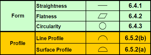
[All material referenced from DCS GD&T Training Manual]
Material modifiers help the designer to better describe what is dimensionally acceptable by providing insight into additional tolerances caused by the presence or absence of material on a part or feature.
TIPS to Remember:
Material Modifiers provide one of three callouts that describe whether a feature contains the maximum or minimum amount of material when fabricated, thus affecting the overall tolerance of the feature.
 MMC - Maximum Material Condition
![]() LMC - Least Material Condition
LMC - Least Material Condition
![]() RFS - Regardless of Feature of Size
RFS - Regardless of Feature of Size
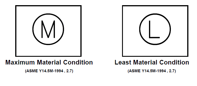
MMC Maximum Material Condition is defined as the condition of a feature which contains the maximum amount of material, that is, the smallest hole or largest pin, within the stated limits of size.
Where a geometric tolerance is applied on an MMC basis, the allowed tolerance is dependent on the actual mating size of the considered feature. The tolerance is limited to the specified value if the feature is produced at its MMC limit of size. Where the actual mating size of the feature has departed from MMC, an increase in the tolerance is allowed equal to the amount of such departure. The total permissible variation in the specific geometric characteristic is maximum when the feature is at LMC. Likewise, referencing a datum feature on an MMC basis means the datum is the axis or center plane of the feature at the MMC limit. Where the actual mating size envelope has departed from MMC, a deviation is allowed between its axis or center plane and the axis or center plane of the datum.
Where a tolerance of position or orientation is applied on a zero tolerance at MMC basis, the tolerance is totally dependant on the actual mating size of the considered feature. No tolerance of position or orientation is allowed if the feature is produced at its MMC limit of size; and in this case, it must be located at true position or be perfect in orientation, as applicable. Where the actual mating size of the considered feature has departed from MMC, a tolerance is allowed equal to the amount of such departure. The total permissible variation in position or orientation is maximum when its feature is at LMC, unless a maximum is specified.
LMC Least Material Condition is defined as the condition in which there is the least amount of material, the largest hole or smallest pin, within the stated limits of size.
Where a positional tolerance is applied on an LMC basis, the allowed tolerance is dependent on the actual mating size of the considered feature. The tolerance is limited to the specified value if the feature is produced at its LMC limit of size. Where the actual mating size of the feature has departed from LMC, an increase in the tolerance is allowed equal to the amount of such departure. The total permissible variation in position is maximum when the feature is at MMC. Likewise, referencing a datum feature on an LMC basis means the datum is the axis or center plane of the feature at the LMC limit. Where the actual mating size of the datum feature has departed from LMC, a deviation is allowed between its axis or center plane and the axis or center plane of the datum.
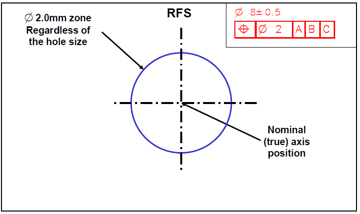
RFS Regardless of Feature Size is the default condition of all geometric tolerances by rule #2 of GD&T and requires no callout. Regardless of feature size simply means that whatever GD&T callout you make, is controlled independently of the size dimension of the part.
Where a geometric tolerance is applied on an RFS basis, the specified tolerance is independent of the actual size of the considered feature. The tolerance is limited to the specified value regardless of the actual size of the feature. Likewise, referencing a datum feature on an RFS basis means that a centering about its axis or center plane is necessary, regardless of the actual size of the feature.
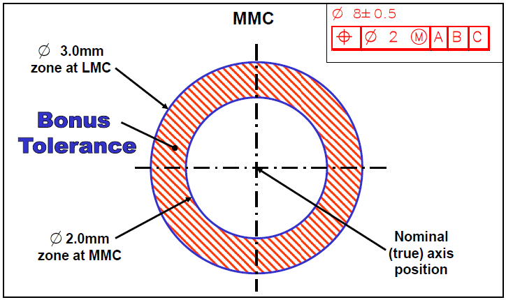
MMC defines the worst case condition of a part that will still guarantee, because it is still within the prescribed tolerances, the assembly between pin(s) and hole(s). When a hole is at its smallest (MMC) and a pin is at its largest condition (also MMC), we can be sure that we will still be able to assemble that part. Thus, MMC is widely used in cases where clearance fits are common.
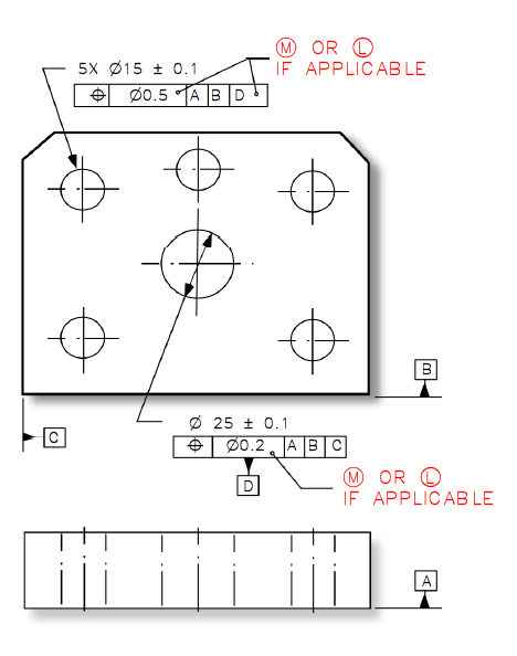
All Applicable Geometric Tolerances (Rule #2). RFS applies, with respect to the individual tolerance, datum reference, or both, where no
modifying symbol is specified. MMC or LMC must be specified on the drawing where it is required.
As the size of the pin departs from MMC toward LMC, a bonus tolerance is added equal to the amount of change. Bonus tolerance equals the difference between the actual feature size and the MMC of the feature.
Bonus Tolerance = MMC - LMC
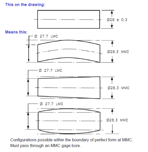
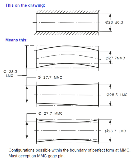
Where only a tolerance of size is specified, the limits of size of an individual feature prescribe the extent to which variations in its geometric form, as well as size, are allowed.
RFS applies, with respect to the individual tolerance, datum reference, or both, where no modifying symbol is specified. MMC or LMC must be specified on the drawing where it is required.
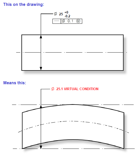
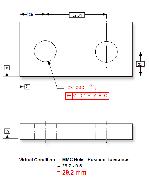
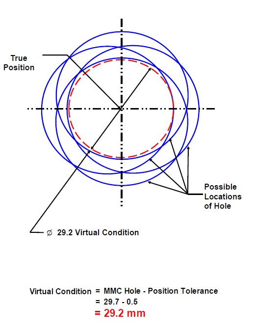
Virtual Condition is defined as the boundary generated by the collective effects of the specified MMC limit of size of a feature and any applicable geometric tolerance. For example, the MMC size of a shaft plus its axial Straightness tolerance, or the MMC size of a hole minus its Position tolerance.
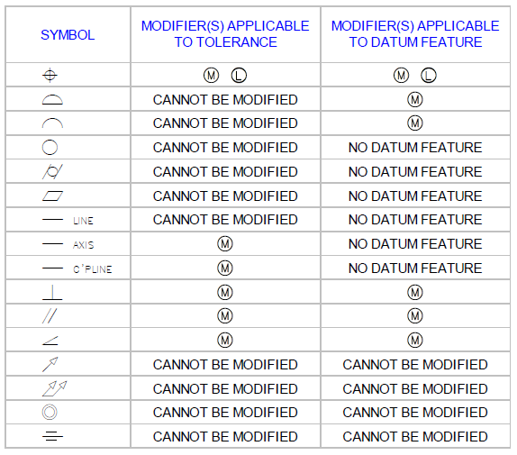
GD&T is applied using symbols and Datums. Click below to see common symbols, and to better understand Datums and Material Conditions
The best to place to start is to discuss implementation with an expert. DCS and its partners across the globe have ASME certified trainers who can discuss implementation, adoption, best practices, and provide training courses to get your people up to speed.

North American Innovation Center
28064 Center Oaks Ct A, Wixom, MI 48393
Call us: +1 (248) 504 6200